I still remember the introduction of a friend’s electronics textbook at university. At least, remember one sentence: “Experience gained is directly proportional to the cost of equipment destroyed”. Going by that theory, I must have gained a lot of experience in Chemistry I, as I broke every piece of my glassware except my Liebig condenser!
This theory led me to deciding I needed to build an over-voltage protection circuit:

In this instance I fortunately curtailed the cost of gaining experience by only frying a Raspberry Pi Zero when I bumped the variable resistor controlling the output of a buck converter and put about 6V into the GPIO 5V pin of the Pi – very quickly frying it. The best antidote to that, I decided would be an over-voltage regulator. My first attempt just involved a Zener diode and a polyfuse, which I found to be quite crude.
After looking around, I found a design I liked more ay Maxim Integrated.
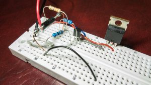
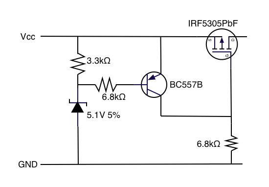
I changed some of the components for items I had more readily available, like using a BC557B PNP transistor (which is really a “common-or-garden” variety of PNP transistor), and performing the main high-side switching with a P-channel MOSFET which I already had available:

I initially started out with a 2.2kΩ resistor, which resulted in the cutoff happening at 4.7 to 4.8V. This circuit cuts out very early in the breakdown of the Zener diode due to the very low current flowing. I found that rather than replacing the Zener diode, it was simpler to change the resistor. With a 3.3kΩ resistor, the circuit was cutting out at about 5.14V, which is fine for my purposes.

